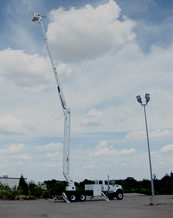
Versalift VST-9000-MHI Articulated / Telescopic Aerial Bucket Trucks with Optional Material Handling
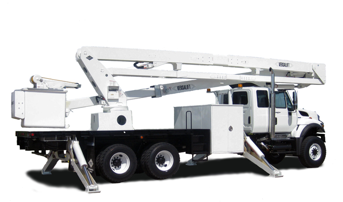
94′ 11″ Working Height
56′ 8″ Horizontal Reach
700 lbs Bucket Capacity with Jib Installed (800 lbs without)
PERSONNEL RESTRAINT SYSTEM – A safety belt or harness and a lanyard are required and can be supplied by Time Manufacturing Company at an additional cost. Consult applicable work practices and regulations to choose between a safety belt and a harness. The anchor for the lanyard is attached to the platform.
INDIVIDUAL LOWER CONTROLS – Individual fullpressure controls at the turret actuate all boom functions. The lower control station is equipped with a selector valve to override the upper controls and serve as the emergency stop from lower controls.
SINGLE STICK UPPER CONTROL – The fullpressure single stick upper control includes a safety trigger to prevent inadvertent operation. The lift movements correspond with control handle movements. An emergency stop and a tool selector control are located at the upper controls.
HYDRAULIC PLATFORM ROTATOR – A hydraulic platform rotator, operated by a control lever, rotates the platform 1800 from one side of the outer/inner boom assembly, across the end-hung position, to the other side of the outer/inner boom assembly.
HYDRAULIC PLATFORM LEVELING – A master and slave cylinder arrangement automatically levels the platform in all boom positions. This system also provides hydraulic platform tilt to adjust platform level, tilt the platform for clean out, or to ease the removal of an injured operator. The platform tilt can be activated from the upper and lower controls.
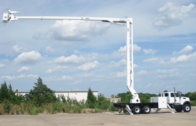 OUTER/INNER BOOM ASSEMBLY – The outer/inner boom assembly includes an outer boom, telescopic inner boom, extension system, and hose assemblies. The outer boom consists of a 12 in. x 14 in. (305 mm x 355 mm) steel section. The inner boom consists of a 9-1/4 x 11-1/4 in. fiberglass section and a 10 x 12 steel section. The fiberglass section provides a 108 in. insulation gap. The inner boom can be easily removed and disassembled for service and inspection. The extension system consists of a hydraulic cylinder, two integral holding valves, and a “cat-track” type hose carrier housed entirely within the boom assembly. The hoses routed through the outer/inner boom assembly are non-conductive and fully contained within the boom assembly. The outer/ inner boom assembly articulates from 250 +/-20 below horizontal to 750 +/-20 above horizontal. Actuated by a double acting cylinder, equipped with two integral holding valves; the outer/inner boom assembly is offset to one side to provide easy access to the platform. A boom support cradle and a boom tie down strap are included.
LOWER BOOM WITH CHASSIS INSULATING SYSTEM – Each end of a high strength fiberglass insert (chassis insulating system) is installed over a rectangular 12 in. x 14-in. (305mm x 355 mm) high strength steel section. The steel and fiberglass sections are bonded with pressure injected adhesive to fill any voids. After the adhesive cures, 32 bolts are installed to assure maximum strength. A compensation link with a fiberglass section maintains the 24-in. (0.61 m) insulation gap in all the boom positions. The double acting cylinder, with an integral holding valve, allows the lower boom to articulate from horizontal to 880 above horizontal.
CYLINDERS – Both the upper and lower cylinders are a threaded head-cap design. Both cylinders are equipped with two integral holding valves to prevent creep down and to lock the booms in position in case of hose failure.
TURRET – The 5/8 in (16 mm) thick turret wings are designed for strength and rigidity. The 1-1/2 in (38 mm) thick turret base plate is machined to provide a flat surface to support the rotation bearing.
CONTINUOUS ROTATION – Unrestricted rotation is accomplished by a hydraulically driven worm and spur gear with a shear-ball rotation bearing. The critical bolts holding the lift to the rotation bearing and the rotation bearing to the pedestal are grade 8 hex head capscrews. These critical bolts are torque seal marked to provide a quick means of detecting any turning of the bolt upon inspection.
LUBRICATION – Non-lube bearings are used at all pivot points. Only the rotation bearing and rotation bearing gear teeth require periodic lubrication. PEDESTAL – The pedestal is rectangular with a reinforced mounting plate. The top plate of the pedestal is 1-1/2 in. (38 mm) thick and machined flat to support the rotation bearing.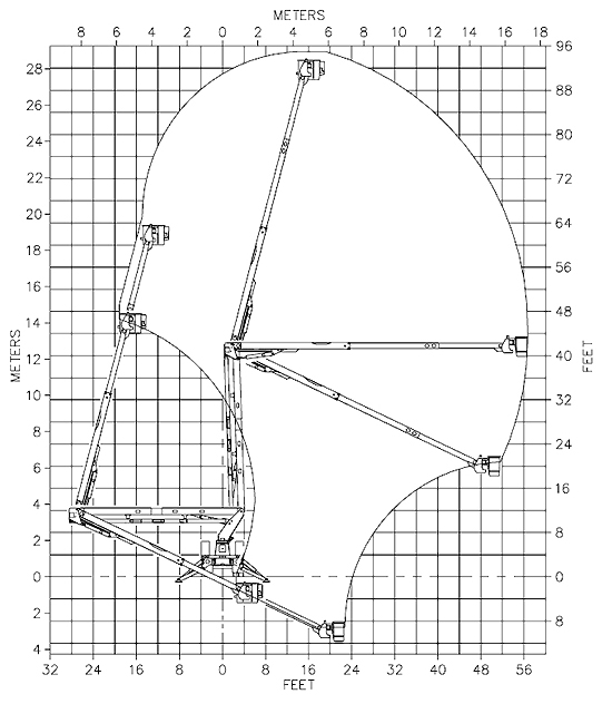
HYDRAULIC OIL RESERVOIR – A 35 gallon (132 l) hydraulic oil reservoir is built integral to the pedestal. The reservoir includes an anti-splash baffle and sight gauge for quick hydraulic fluid level checks, and a return filter pressure gauge.
HYDRAULIC SYSTEM – The open-center hydraulic system operates at 3000 psi (205 bars) at 10 gpm (38 lpm). A 10-micron return-line filter, mounted above the hydraulic oil level and inside the pedestal, can be easily changed without draining the reservoir. A filter gauge with a color-coded range is used to monitor the condition of the return line filter for replacement. The 100 mesh (149 micron) suction strainer in the reservoir can be removed for cleaning. A gate valve, located below the reservoir, prevents oil loss when the pump is serviced. A magnetic drain plug attracts metal particles from the oil.
TWO-SPEED MANUAL THROTTLE CONTROL – Changes the engine/pump speed to give the operator a choice between slow and normal boom speeds, and also at slow speed provides reduced flow to operate hydraulic tools. The manual throttle control is designed to operate only when the truck engine is running and the master control is activated. An air cylinder at the platform or a toggle switch at the turret can be used to energize the manual throttle control. PAINT – The complete unit is primed and painted before assembly. The standard color is white urethane.
HOSES AND FITTINGS – The hoses routed through the booms are high pressure and non-conductive with swaged hose end fittings. Nylon sleeves are installed over hoses at points of movement. Reusable fittings can be installed if a hose is damaged.
ENGINE START/STOP – The start/stop circuit has been designed so the lift cannot be operated unless the truck ignition switch is in the “RUN” position and the master control is activated. This feature makes it difficult for unauthorized individuals to operate the lift when the truck is locked. An air cylinder at the upper controls and a toggle switch at the pedestal energize this system.
HYDRAULIC TOOL CIRCUIT AT THE PLATFORM – This system is designed for open center hydraulic tools. The tool circuit provides approximately 6 gpm at engine idle and 10 gpm with the throttle control engaged. The tool pressure is 2000 psi (140 Bars).
GENERAL SPECIFICATIONS (Note: All dimensions and angles are nominal, based on 40 in. (1.02m) frame height.)
| VST-9000-I | |
| Horizontal Reach | 56 ft 8in (17.3m) |
| Maximum Platform Capacity | 800 lbs (360kg) |
| Maximum Platform Capacity with Optional Jib Installed | 700 lbs (317kg) |
| Lower Boom Lift Eye Capacity (Optional) | 1500 lbs (680kg) |
| Maximum Jib Capacity (Optional) | 1000 lbs (454kg) |
| With Standard Pedestal | |
| Height to Bottom of Platform | 89 ft 11 in. (27.4m) |
| Working Height | 94 ft 11 in. (28.9m) |
| Stowed Travel Height | 12 ft 5 in (3.8m) |
| Hydraulic System | |
| Operating Pressure | 3000 PSI (205 Bars) |
| Flow Rate | 10 GPM (38 lpm) |
| Filtration | 10 micron return 100 mesh section |
| System Type | Open center |
| Power Source | PTO Pump |
- Specifications may vary without prior notification
- Required GVWR can vary significantly with chassis, lift mountings location, service body, accessories, and desired payload.

