Versalift LT-56 / LT-62 Telescopic Aerial Lift
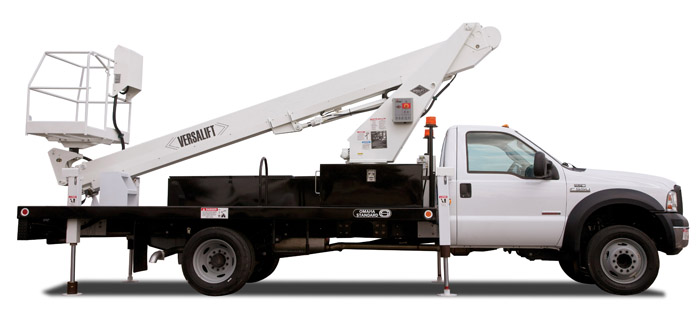
PLATFORM
The standard platform is 49 in. x 33 in. x 43 in. (1.25 X 0.85 X 1.1m) (l x w x h) with a step-through opening for easy access. The maximum platform capacity is 440 lbs (200 kg). Platform leveling is controlled automatically by amaster and slave cylinder arrangement and 180° hydraulic platform rotation is standard.
ROTATION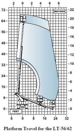
Rotation is continuous and unrestricted in either direction. An electric and hydraulic collector assembly provides the path for hydraulic oil and electric signals from thepedestal to turret. A hydraulically driven worm and spur gear and a shear-ball rotation bearing accomplish rotation. The critical bolts holding the turret to the rotation bearing and the rotation bearing to the pedestal meet SAE grade 8 specifications. These critical bolts are Torque Seal Marked to provide a quick means to inspect for loosening. An adjustment screw is provided to adjust pinion and rotation gear clearances.
HYDRAULIC SYSTEM
The open center hydraulic system operates at 2250 psi (158 kg/cm2) at 3 gpm (11 lpm) . The pump draws oil through a 100 mesh suction strainer that is equipped with a bypass valve. A 10-micron return filter with shut-off valve is included. This system is powered by the chassis transmission power take off.
PAINTING
The complete unit is primed and painted prior to assembly. White enamel paint is standard.
CYLINDERS
The extension cylinder has wear rings on the piston and end gland for extended seal life. Dual holding valves are mounted at the extension cylinder base to prevent boom creep during travel or uncontrolled movement in case of hydraulic hose failure. The boom elevation cylinder also has a dual holding valve.
EMERGENCY POWER
This system consists of a hydraulic pump driven by a DC motor, which is powered by the truck engine battery. The system is connected in parallel with the main pump and is designed for non-continuous operation. Toggle switches are used to energize the system at the upper and lower controls. Emergency power is only available when the primary power source is not operating.
BOOM & CYLINDER PINS
Pins are high strength alloy steel and chrome plated for a hard finish and corrosion resistance. Cylinder pins are held in place with Torque Seal marked bolts at one end and a pin cap bolted to the other end.
UPPER CONTROLS
The upper controls are mounted to the outside of the platform and include a guard to prevent damage and inadvertent operation. The boom functions are operated by fully feathering joysticks with safety triggers. Auxiliary functions are operated by color coded push button switches. An emergency stop palm button is also provided. The emergency stop kills power to the controls, control valve, and stops the chassis engine.
LOWER CONTROLS
The lower controls are mounted to the side of the turret. A key switch selects upper or lower control operation. Toggle switches operate all boom functions at reduced speeds. An emergency stop palm button is also provided. The emergency stop kills power to the controls, control valve, and stops the chassis engine.
LUBRICATION
Fiberglass-Teflon non-lube bearings are used at all points of motion. The rotation bearing is the only component that requires periodic lubrication.
GENERAL SPECIFICATIONS (Based on 40 in (1.02m) Frame Height)
| Versalift LT-56 | Versalift LT-62 | |
| Height to Bottom of Platform | 57 ft 11 in (17.65m) | 63 ft 11 in (19.48m) |
| Working Height | 62 ft 11 in (19.18m) | 68 ft 11 in (21.01m) |
| Horizontal Reach | 26 ft 3 in (8.0 m) | 26 ft 3 in (8.0m) |
| Approx. Stowed Travel Height | 11 ft 11 in (3.63m) | 11 ft 11 in (3.63m) |
| Maximum Rated Platform Capacity | 440 lbs (200 kg) | 440 lbs (200 kg) |
| Hydraulic System | ||
| Operating Pressure | 2250 PSI (158 kg/cm2) | 2250 PSI (158 kg/cm2) |
| Flow Rate | 3 GPM (11 lpm) | 3 GPM (11 lpm) |
| Filtration | 10 micron return | 10 micron return |
| System Type | Open center | Open center |
| Reservoir Capacity | 30 gal (113 l) | 30 gal (113 l) |
*NOTE:
- Specifications may vary without prior notification
- Required GVWR can vary significantly with chassis, lift mountings location, service body, accessories, and desired payload.
- PNEUMATIC CIRCUIT TO THE PLATFORM
- PERSONNEL RESTRAINT SYSTEM
- INDEPENDENT H-FRAME OUTRIGGERS
- INDEPENDENT A-FRAME OUTRIGGERS
- REMOTE RESERVOIR
- 120V WIRING
- OUTRIGGER BOOM INTERLOCK SYSTEM
- ADDITIONAL SLIP RINGS
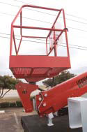
Easy access bucket
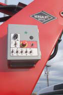
Ground controls conveniently mounted on lower boom
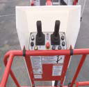
The work platform allows
easy access while providing user-friendly controls
for smooth maneuverability.
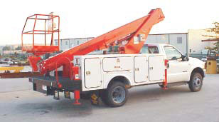
Mounting on standard chassis with low stowed height simplifying transit and operation.

