Versalift Tel-31/35-NE Telescopic Aerial Bucket Trucks
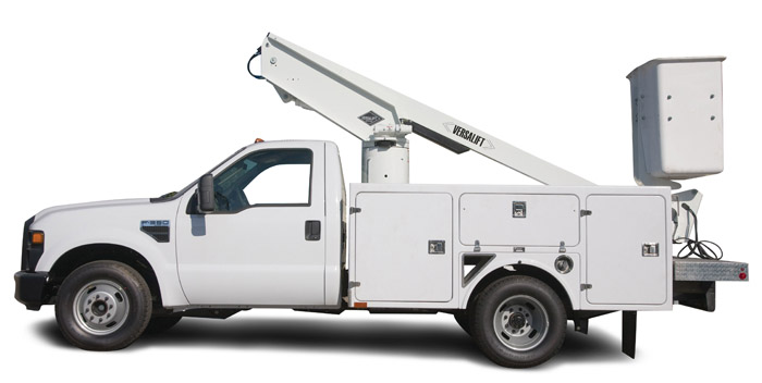


The Versalift TEL-31/35-NE aerial device provides an end mounted two man platform. The following is a brief description of the major components of the TEL-31/35-NE aerials.
PLATFORM – The standard platform is steel 49 in X 33 in. X 43 in. (1.25 m X 0.85 m X 1.1m) with a step through opening for easy access. The maximum platform capacity is 440 lbs. (200 kg).
HYDRAULIC LEVELING – Platform leveling is controlled automatically by a master and slave cylinder arrangement. The platform leveling system can be manually activated from the upper or lower controls to level the platform, to stow and unstow the platform, or to tilt the platform for clean out and rescue.
OUTER/INNER BOOM ASSEMBLY – The major components of the outer/inner boom assembly include an outer boom, a telescoping inner boom, an extension cylinder, a hose carrier system, and slide pads mounted on the inner and outer boom. The outer boom consists of an 6 in. X 8 in. (152 mm X 203 mm) rectangular high strength steel section. The telescoping inner boom consists of a 5 in. X 7 in. (127 mm 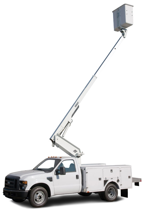 X 178 mm) rectangular aluminum section. The inner boom does not have to be removed to service the extension cylinder or slide pads. The extension system consists of a hydraulic cylinder with wear rings on the piston and end gland and a holding valve mounted to the cylinder base. The hose carrier system is a multi-link assembly with adequate space to carry hoses and wiring to the upper control station. Ultra high molecular weight plastic slide pads mounted on the inner boom can be changed without removing the inner boom. The outer boom side and top slide pads are infinitely adjustable and the lower pad can be replaced without removing the inner boom. The telescoping outer/inner boom assembly articulates from 25o below horizontal to 80o above horizontal. A double acting cylinder, equipped with a counter balance holding valve provides boom elevation. A boom support cradle and a ratchet-type boom tie down strap are included.
CONTROL VALVE – The system pressure relief, hydraulic leveling, variable speed, and the electric/hydraulic boom function valves are a single integrated system and mounted on the turret wing. Electric lower controls which override the upper controls are located below rotation.
CYLINDERS – The extension cylinder has wear rings on the piston and end gland for extended seal life. A double acting holding valve is mounted at the extension cylinder base to prevent boom creep during travel or uncontrolled movement in case of hydraulic hose failure. The extension cylinder can be removed without removing the inner boom. A hydraulic regeneration feature on the extension cylinder provides extension and retraction at approximately the same speed. The boom elevation cylinder has a single acting holding valve.
ROTATION – Rotation is 360o non-continuous with an electric limit switch to prevent hose and wiring damage. Rotation is accomplished by a hydraulically driven worm and spur gear and a shear-ball rotation bearing. The critical bolts holding the turret to the rotation bearing and the rotation bearing to the pedestal meet SAE grade 8 specifications. These critical bolts are Torque Seal Marked to provide a quick means to inspect for loosening. An adjustment screw is provided to adjust pinion and rotation gear clearances.
HYDRAULIC SYSTEM
The hydraulic system can be powered by the chassis-engine, a chassis-transmission power take-off or more advanced options.
LUBRICATION
Non-lube bearings are used at all pivot points. The rotation bearing is the only component that requires lubrication.
GENERAL SPECIFICATIONS (Based on 40 in (1.02m) Frame Height)
| Tel-31-NE | Tel-35-NE | |
| Horizontal Reach | 16 ft 7 in (5.05m) | 20 ft 7 in (6.27m) |
| Rated Platform Capacity | 440 lbs (200kg) | 440 lbs (200kg) |
| Outer Boom Travel | -25° to +80° | -25° to +80° |
| Inner Boom Extension | 92 in. (2.34m) | 116 in. (2.95m) |
| Ambient Temperature Range for Structural Integrity | -40°F (-40°C) to 125°F (52°C) | -40°F (-40°C) to 125°F (52°C) |
| With Standard Pedestal 1 | ||
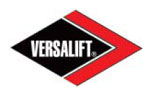
| Height to Bottom of Platform | 30 ft 11 in (9.42m) | 34 ft 11 in (10.64m) |
| Working Height | 35 ft 11 in (10.64m) | 39 ft 11 in (12.17m) |
| Stowed Travel Height | 10 ft 10 in (2.97m) | 10 ft 10 in (2.97m) |
| Weight of Lift w/ Mounting Hardware2 | 1545 lbs (701kg) | 1575 lbs (714kg) |
| 6 In (152mm) Taller Pedestal 1 | ||
| Height to Bottom of Platform | 31 ft 5 in (9.58m) | 35 ft 5 in (10.80m) |
| Working Height | 36 ft 5 in (11.10m) | 40 ft 5 in (12.32m) |
| Stowed Travel Height | 11 ft 4 in (3.45m) | 11 ft 4 in (3.45m) |
| Weight of Lift w/ Mounting Hardware2 | 1560 lbs (708kg) | 1590 lbs (721kg) |
| 12 In (305mm) Taller Pedestal 1 | ||
| Height to Bottom of Platform | 31 ft 11 in (9.73m) | 35 ft 11 in (10.95m) |
| Working Height | 36 ft 11 in (11.25m) | 40 ft 11 in (12.47m) |
| Stowed Travel Height | 11 ft 10 in (3.61m) | 11 ft 10 in (3.61m) |
| Weight of Lift w/ Mounting Hardware2 | 1575 lbs (714kg) | 1605 lbs (728kg) |
- Heights based on 40 in. (1.02m) frame height with bottom of pedestal mounted 5 in. (127mm) above the top of the frame.
- Weight based on standard lift configuration and 125 lbs (56.7kg) mounting hardware.
- Specifications may vary without prior notification
- 180 degree Hydraulic Platform Rotation
- Emergency Power
- Individual Upper Controls
- Two man Steel or Fiberglass Platform Available.
- 6″ or 12″ Taller Pedestal
- 360 degree Turret Rotation
- Electric Single Stick Control
Hydraulic leveling allows for
simplified clean outor safe
removal of an injured operator.